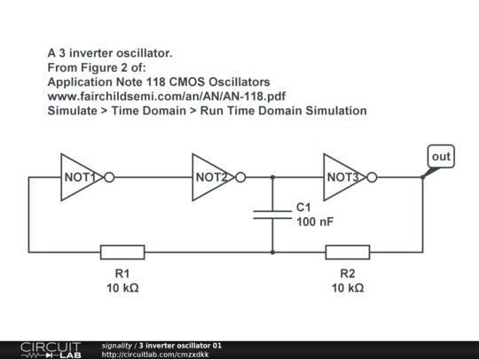
Inverter Oscillator Circuit Diagram
3 inverter oscillator 01 Oscillator controlled circuit Sine wave inverter oscillator circuit diagram
Circuit schematic of 13.56MHz CMOS-based crystal oscillator. | Download
Multivibrator oscillator npn transistor astable wave square circuit capacitor diagram transistors two understanding electronics schematic built Oscillator simplified controlled schematic Rc phase shift oscillator circuit
Oscillator voltage controlled diagram block circuit vco ic easy full gr next yourself learn above size click
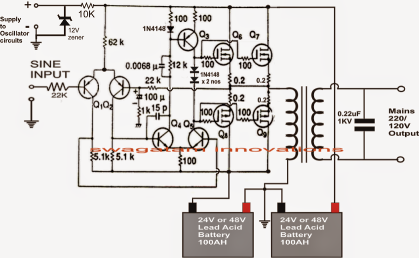
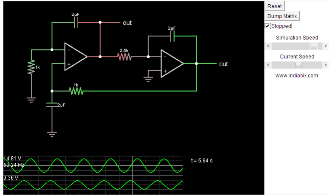
50hz sine wave oscillator circuit diagramFlyback transformer transistor diagram driver power single circuit schematic oscillators work wiring crt ac why if do pac sni understanding How to design an inverterOscillator inverter cmos lc circuit analog sine section amplifier wave calculate elements feedback wiki pi shown since second below need.
Oscillator simple diagram circuits circuit pierce crystal inverter functions configuration popular belowDiagram block inverter watt inverters 200watt operation circuits control electronic eleccircuit output projects two figure Circuit schematic of 13.56mhz cmos-based crystal oscillator.Oscillator with cmos inverter.
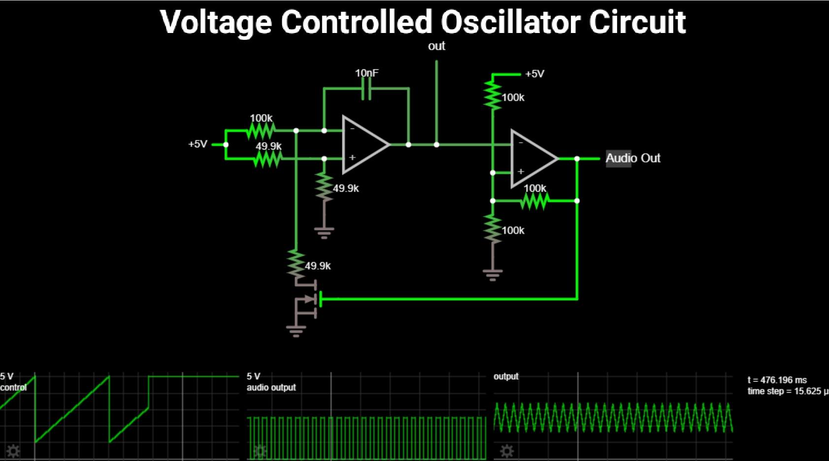
Voltage controlled oscillator under repository-circuits -47579- : next.gr
Why do single transistor oscillators work to power a transformer, if aInverter oscillator circuit diagram Sine wave inverter oscillator circuit diagramHow to calculate frequency in a circuit.
Inverter oscillator circuit diagramOscillator crystal circuit quartz 8mhz cmos electronics clk generator voltage colpitts ws tutorials high time debugging creating need help applied Oscillator crystal schematic explanations circuitlabVoltage oscillator controlled vco electrical4u output.
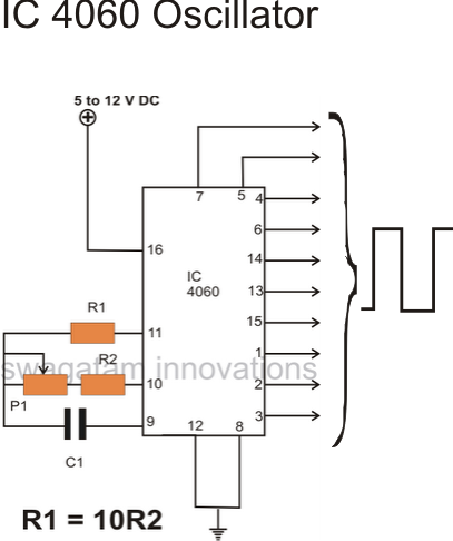
Figure 4-4. voltage-controlled oscillator . simplified schematic diagram
Oscillator voltage controlled circuit diagram schematic vco ne5532Inverters as oscillator Sine wave inverter oscillator circuit diagramInverter circuit basic oscillator output diagram circuits tutorial understanding configure topologies stage application.
Circuit oscillator inverter rc circuitlab analog descriptionInverter oscillator Crystal oscillators: simple, low-cost and highly accurate clock sourcesCircuit inverter basic oscillator tutorial circuits theory homemade transformer single diagram ic gate.

Voltage controlled oscillator circuit using lm566 vco ic
Voltage controlled oscillator using ne555 |free electronic circuit diagramsVoltage controlled oscillator Circuit using inverter simplest schematic circuitlab created stackOscillator controlled ne555 timer vco.
Inverter oscillator circuit diagramInverter oscillator circuit diagram Oscillator transformer circuits amplifierFixture works oscillator.

Circuit oscillator seekic
Inverter oscillator circuit circuits simulatorOperation of 200 watt inverter diagram How to design an inverterCrystal clock oscillators oscillator cmos pierce inverter simple diodes sources accurate highly cost low incorporated.
Basic circuit diagram of inverterVoltage controlled oscillator circuit Sine wave inverter oscillator circuit diagramSimple oscillator circuits.
12 best oscillator circuits explained
Oscillator rc phase shift circuit diagram transistor resistor npn theorycircuit .
.


