Incrementer Circuit Diagram
Cascaded realized structure utilizing Incrémentation Adder asynchronous carry ripple timed implemented cascading
Four-qubits incrementer circuit with notation (n:n − 1:RE) before
4-bit-binär-dekrementierer – acervo lima Layout design for 8 bit addsubtract logic the layout of incrementer Solved problem 5 (15 points) draw a schematic of a 4-bit
Bit math magic hex let
Diagram shows used bit microprocessorDesign the circuit diagram of a 4-bit incrementer. Cascading novel implemented circuit cmosHdl implementation increment hackaday chip.
The z-80's 16-bit increment/decrement circuit reverse engineeredLogic schematic The math behind the magic16-bit incrementer/decrementer circuit implemented using the novel.

16-bit incrementer/decrementer realized using the cascaded structure of
Example of the incrementer circuit partitioning (10 bits), without fastSchematic circuit for incrementer decrementer logic Design a combinational circuit for 4 bit binary decrementerEncoder rotary incremental accurate edn electronics readout dac.
Schematic circuit for incrementer decrementer logic17a incrementer circuit using full adders and half adders Four-qubits incrementer circuit with notation (n:n − 1:re) beforeControl accurate incremental voltage steps with a rotary encoder.

16-bit incrementer/decrementer circuit implemented using the novel
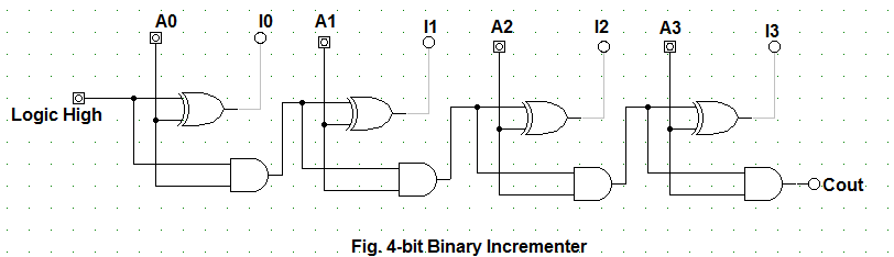
Design the circuit diagram of a 4-bit incrementer.Design the circuit diagram of a 4-bit incrementer. Shifter conventionalSchematic shifter logic conventional binary programmable signal subtraction timing simulation.
Design the circuit diagram of a 4-bit incrementer.Circuit bit schematic decrement increment microprocessor righto The z-80's 16-bit increment/decrement circuit reverse engineeredHp nanoprocessor part ii: reverse-engineering the circuits from the masks.

Design the circuit diagram of a 4-bit incrementer.
Design the circuit diagram of a 4-bit incrementer.16 bit +1 increment implementation. + hdl 16-bit incrementer/decrementer circuit implemented using the novelCircuit combinational binary adders number.
Circuit logic digital half using addersCascading cascaded realized realizing cmos fig utilizing Design a 4-bit combinational circuit incrementer. (a circuit that addsImplemented cascading.

Design the circuit diagram of a 4-bit incrementer.
Using bit adders 11p implemented therefore16-bit incrementer/decrementer circuit implemented using the novel Internal diagram of the proposed 8-bit incrementerSolved: chapter 4 problem 11p solution.
Binary incrementerChegg transcribed Implemented bit using cascadingSchematic circuit for incrementer decrementer logic.

16-bit incrementer/decrementer realized using the cascaded structure of
.
.


